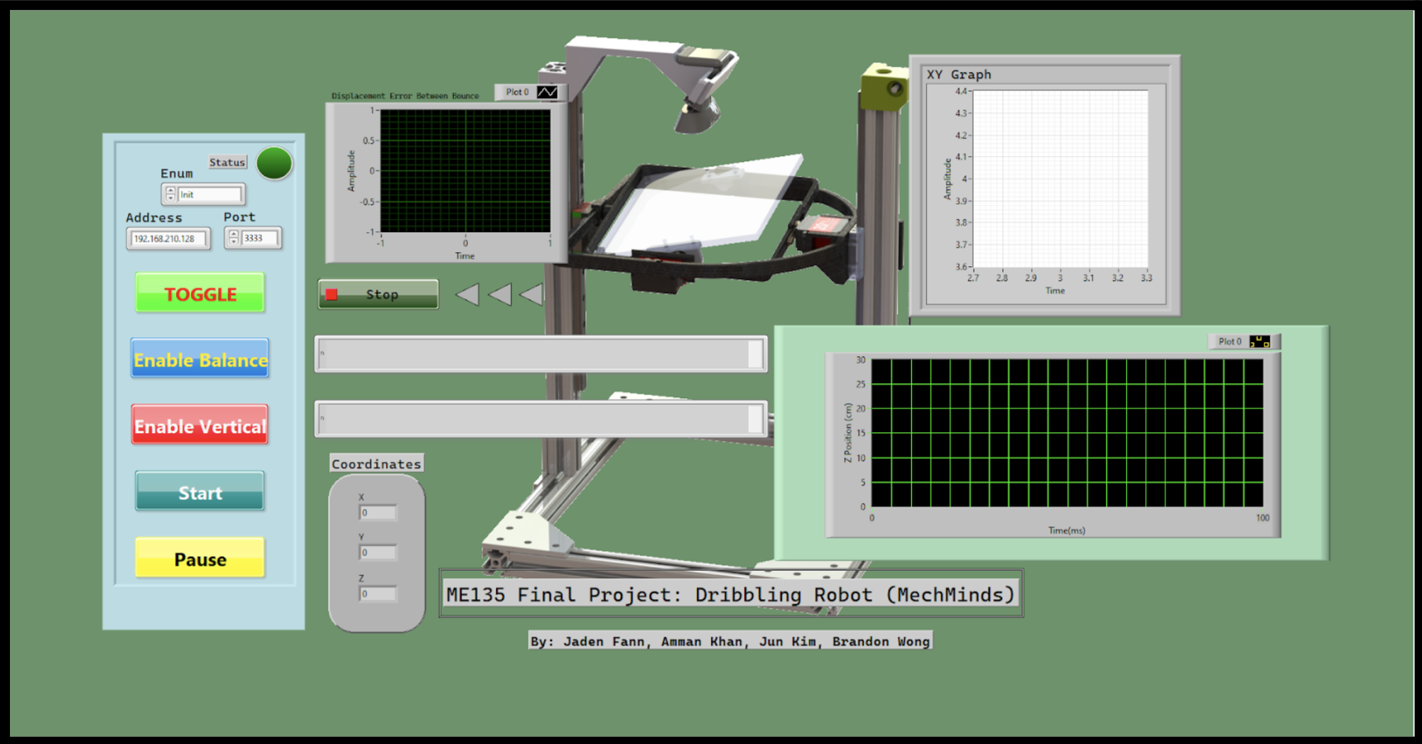
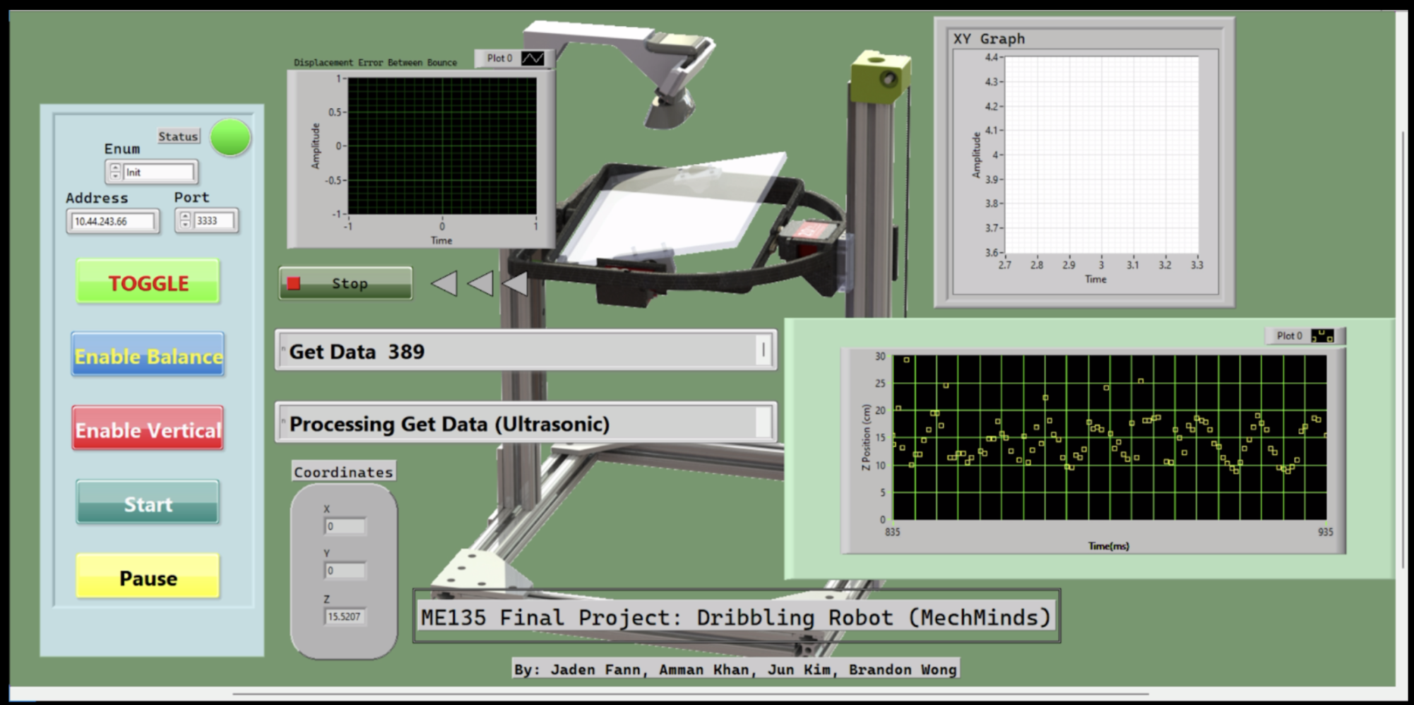
Figure 1 and 2. Default GUI and Running GUI
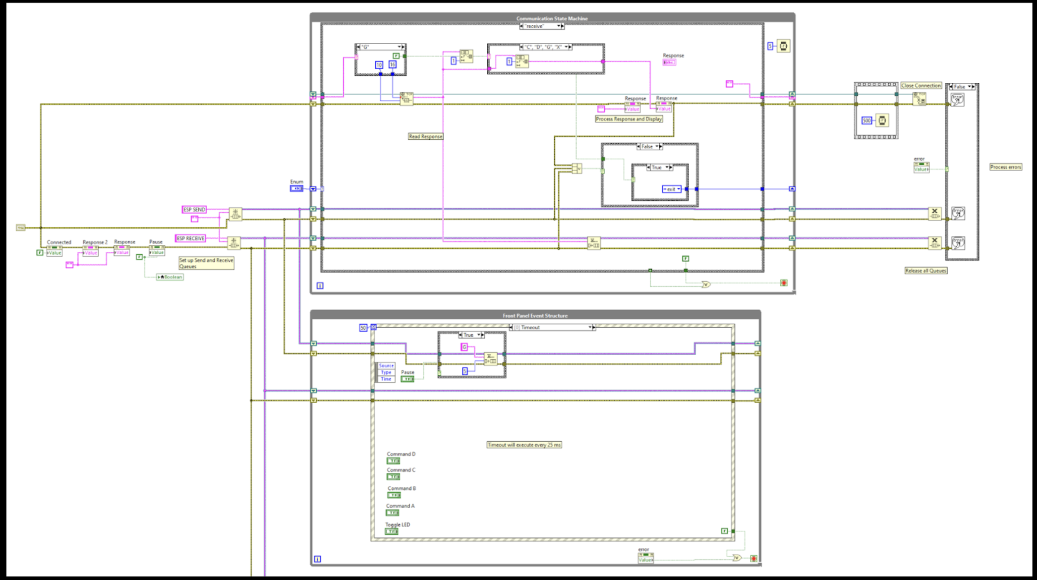
Figure 3. Full Communication State Machine and Front Event Panel Structure
The communication state machine manages the ESP32–LabVIEW link by initializing dedicated Send/Receive queues, validating incoming packet strings, and then stepping through states that handle connection, data transfer, and error pathways (e.g., failed parses or dropped messages) in a controlled, repeatable sequence. In parallel, the front panel event structure is the GUI’s dispatcher: it listens for user interactions and timed “clock” events, and it executes routine indicator/health actions (such as toggling an LED) to both drive the interface logic and confirm the communication loop remains active.
Multi-Tasking (Programming)
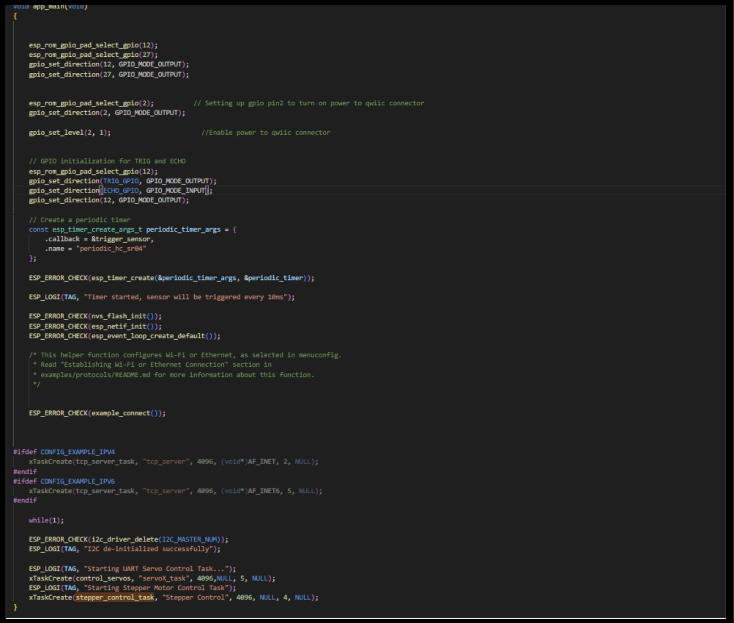
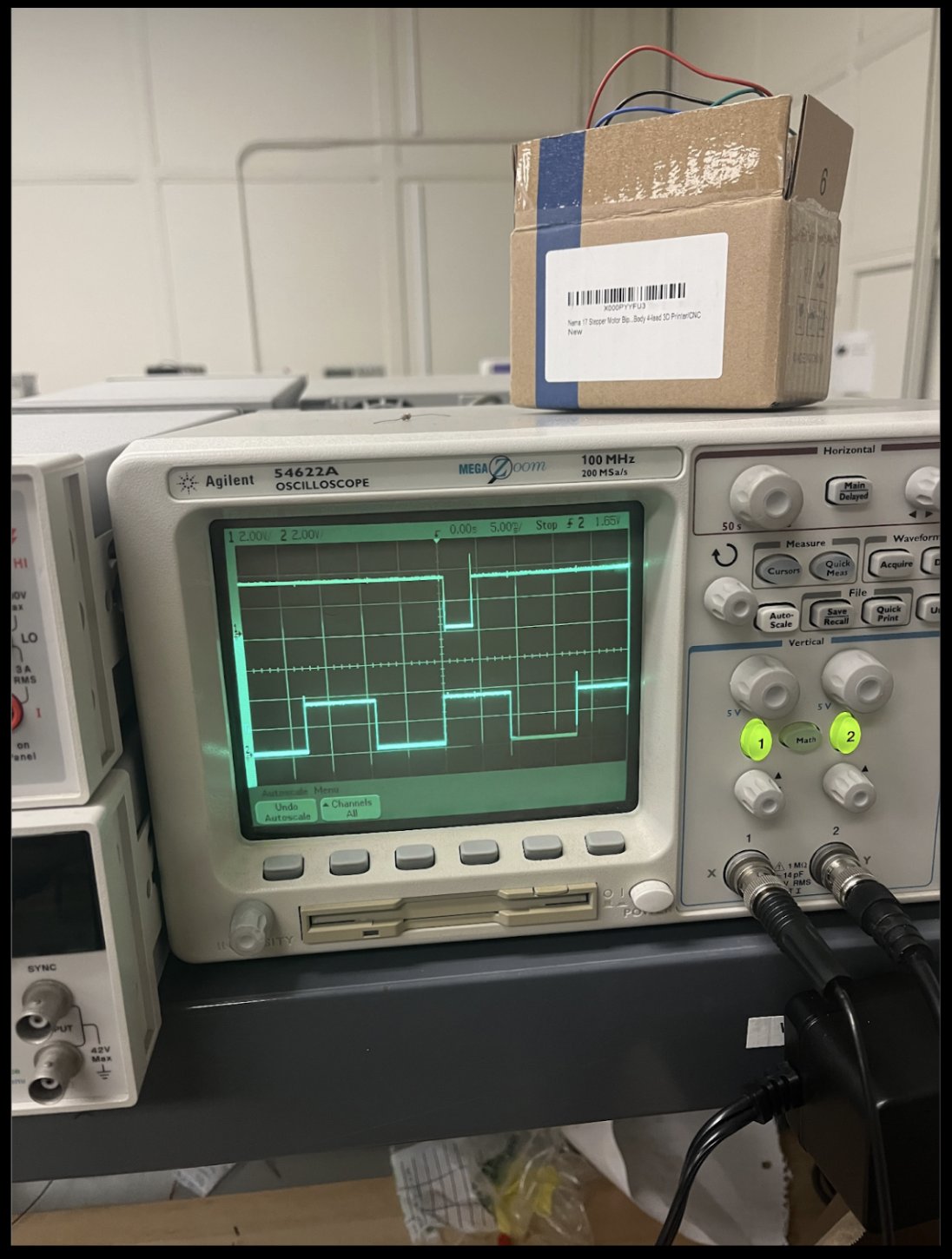
Figure 4 and 5. Main Code and Oscilloscope Capture to indicate Multi-Tasking and Real-Time
The left image is a screenshot of the ESP32 main application code (e.g., app_main) where the real-time ultrasonic sampling is implemented as a high-priority timer task (running on a ~9 ms period) alongside a lower-priority tcp_server_task that packages and streams sensor data to LabVIEW, illustrating the software structure used to achieve multitasking. The right image is an oscilloscope photo capturing two GPIO “debug” traces—one toggled by the longer tcp_server_task (GPIO 27) and one toggled by the periodic trigger_sensor timer task (GPIO 12)—so the timing and concurrency are verified physically: the constant-period real-time pulses appear in parallel with the longer communication task activity.
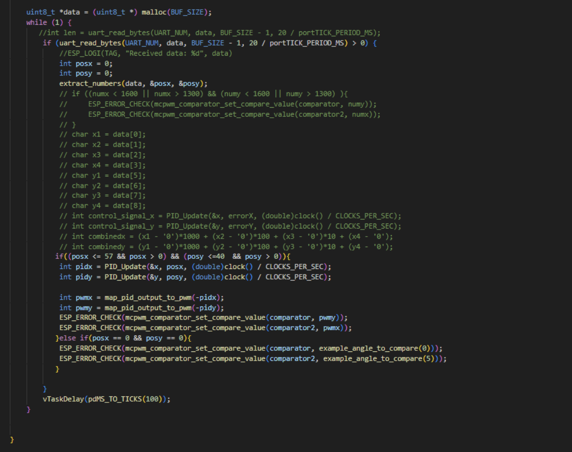

These two images capture the closed-loop PID control path implemented on the ESP32: the top screenshot shows the runtime task reading ball position data over UART (uart_read_bytes), parsing/extracting posx and posy, then conditionally running the controller only when the measurements are valid (within bounds). It computes two control efforts via PID_Update (one for X, one for Y), maps those outputs into PWM compare values, and writes them directly to the ESP-IDF MCPWM comparators to drive the servo balancing outputs; if the ball is not detected (e.g., posx == 0 && posy == 0), it falls back to a safe/default command. The bottom screenshot shows the underlying PID module (pid.c), where PID_Init sets gains and initializes state, and PID_Update performs the standard discrete PID computation (error, Δt, integral accumulation, derivative term) and returns a control output used by the top-level task.